Friday, October 1, 2010

Getting into polypropylene


In which your narrator begins to familiarise himself with the vagarities of printing with polypropylene.

I cut a 3/8 inch black HDPE print bed for printing polypropylene (PP). PP doesn't stick all that firmly to it but it should be adequate for my purposes. Before getting into designing and printing ligaments, I decided to just do some sample prints to get used to how it behaves and what the settings are.

I found that my ABS temperature settings were quite adequate for PP. PP does, however, tend to swell after leaving the extruder orifice considerably more than ABS. Whereas ABS swells from the 0.3 mm orifice to 0.458 mm, PP at the same temperatures and extruder stepper rates swells to 0.58 mm. This means that you're running 60% more PP through the extruder than you are ABS for identical extruder settings. That quickly became apparent with several trial prints.

Just for fun I printed the middle finger metacarpal.


The print didn't have the fine definition of ABS, but then I don't have the flow compensated completely for the faster flow rate that PP does.  The metacarpals were quite flexible.

I printed a few flat plates of PP several layers thick with no raft and it appears that PP will work very well for ligaments.

Monday, September 27, 2010

First prints


After having separated out the individual bones from the hand scan, I decided to print a couple of copies of the middle finger from metacarpal to distal phalange.

Preparing the phalanges for print was undertaken without drama in AoI by using a single block and boolean operations to slice each phalange into lower and upper halves.


The next step involves the printing of flexural joints and ligaments in polypropylene to the ABS bones.  Hopefully, the attachment of the ligaments to the bone will be simplified by the use of a special adhesive that I've located.  That is on order and should arrive early next week.

Sunday, September 26, 2010

Dem Bones


In which your narrator creates a way to separate parts from an undifferentiated OBJ file scan of the bones in a human hand.

Recently, I came to the conclusion that it was going to be very difficult to achieve anything like the degrees of movement with a human hand in anything like the same size as a natural hand. The Shadow Robot Company gets about as close as you can get by achieving 20 of the 27 degrees of freedom possible with the human hand.


If you look at the kinematics of the hand, which are the best in the industry, you'll notice what amount to pin joints.  While I have no trouble with them, they're extremely hard to do with printed ABS.  As a result, I've begun to look at a more biomimetic approach which has had me looking much more closely at how a hand is put together.


When you look closely at how the joins and joints in the hand are put together you see a series of strip ligaments applied like bandages to the joints to restrict and control movement.  Oddly, the colouring of the Gray's Anatomy drawing twigged my thinking.  The bones are pretty much the same yellowish tint that the ABS I print turns to several weeks after being printed.  The grey-white of the ligaments looks just like the polypropylene that I did a bit of work with a while back.

I found polypropyene a bit too rubbery for my purposes back then but then I realised that polypropylene is famous for being useful as a plastic that can stand flexing, a perfect match for ligaments.  As well, there was the small matter that I'd acquired some 80 lbs of 3 mm polypropylene filament over a year ago at a clearance sale for about $1/lb.

What if I made bones out of ABS and ligaments out of polypropylene?  With the powerful Rapman extruder there was no systems limits on that approach.

First, I had the problem of finding a proper depiction of the bony structure of the human hand.  Several hours with Google led me to this offering from Turbosquid.


Search as I might I was not able to find an open source scan of the human skeleton or parts thereof.  The Turbosquid depiction was inexpensive {please don't write me about better deals, I suspect I've already found them} which suited my tightfisted Scots-Irish nature, but the product was presented as one OBJ file, which made separating out the individual bones a rather daunting task.  Most firms like Turbosquid provide their scans in a variety of formats, most of which work with expensive 3D CAD systems leaving only the OBJ file, which doesn't have intrinsic parts separation, available for use in my preferred 3D CAD system, Art of Illusion (AoI).


I continued my Google search and discovered that if you wanted the bones disarticulated you wound up paying several thousand dollars for a whole skeleton scan.  That was a non-starter.  Thus, I was left with trying to figure out how to separate the parts.  My first notion was to use cutting blocks in AoI.  A few goes at that showed that it was entirely possible but extremely fiddly work.

I then began to wonder how big a task it would be to go in and separate the individual bones in the OBJ file?

The OBJ file format is a rather primitive one that simply includes a list of the 3D points in the point cloud describing the surface of the object(s) followed by a list of triangles containing all the points which make a surface mesh over the object(s) described in the file.  The OBJ format specification is a rather mutable thing and the Turbosquid specification included a lot of textural data and a peculiar triangle specification affectation that I'd never seen before.  Fortunately, when I imported the hand bones OBJ into AoI and then exported it again, it came out in the simple, elegant AoI format.

I wrote a small Visual Basic .NET app to separate out the bones in VB.NET 2008 Express, a powerful development environment which is distributed free by Microsoft.

How it works

The process I followed can be described...

Initially:  break the OBJ file into two lists, the point cloud {List 1} and the triangles descriptions {List 2}.

  1. take the first triangle in the triangle list and put it into a fourth list (List 4) and delete it from List 2.
  2. get the three pointers from the triangle and put them into a third list (List 3) that is sorted from smallest to largest.
  3. Collapse List 3 to include only unique pointers
  4. Take the first pointer out of List 3, delete it from the list and then find all triangle descriptions in List 2 that contain the pointer and add those to List 4 and delete them from List 2.  Add the pointers in each of those triangle descriptions to List 3 and collapse the list again.
  5. Repeat 4 until List 3 is empty.  You've now got the list of triangles describing one of the pieces in List 3.
  6. When List 3 is empty, create a separate OBJ file for the individual piece by copying List 1 followed by List 4 into an individual file.
  7. When this is done Repeat the process starting at 1 until there are no triangles left in List 2.
You will then have an OBJ files for each unique, separate piece in the combined OBJ file that you started with.  AoI doesn't care if there are unused points described in the point cloud.  If you want to get rid of superfluous points you have merely to import the individual OBJ files into AoI and export them again.  This does not happen, apparently, if you import the OBJ file and then try to immediately export it as an STL file.

I've zipped up the code for this little app and put it on my website.  You can access it here.

The hand bone assembly from Turbosquid is not included in that as I read the license I can't redistribute it in its original form.  I'm not sure about that, but I'm not into having that kind of drama with them.

Walking through the app

I'm assuming that you have some familiarity with VB.NET and want to run it from the development environment.  Understand that I'm not happy acting as a help desk for my code.  If you want to use it you're largely on your own.  That said, I'll give you a little walk-through.

Here is what you see when you activate the app.


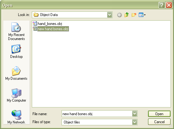
When you punch the open object file button you're taken to the Object Data folder within the app. 


You can navigate to other folders but this is the default folder that is opened.  You select and open the OBJ file you want to break up.  That leaves you with something that looks like this...


...with the point cloud descriptor in List 1 and the triangle descriptors in List 2.  When you've done that you then punch the Separate Parts button and wait for it to finish.  It's pretty fast on my machine, but it can take a while depending on the complexity of what you are trying to separate.

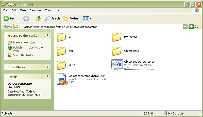
Once it's done you can go find the Output folder which you can see here...
.


You can also see the Object Data folder in this pic.

Looking inside the Output folder, you will see that your original OBJ file has been broken into as many numbered files as there parts in your original OBJ file.


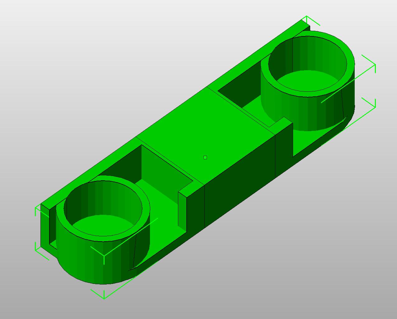
You can then take those into AoI and convert them to STL files for use with either my own Slice and Dice app, Skeinforge, Netfabb or any of the other apps that prepare print files from STL files.

You can see how this separation process works by looking at the #12 file of the hand assembly.


Like most of my work, I'm more interested in demonstrating methods and approaches than in creating out-of-the-box apps.  I know most of you are much more interested in Java, the good Lord save you, and Python than the Wintel-only Visual Studio and Visual Basic development environment.

Have fun!  :-D

Thursday, September 16, 2010

Ball and socket joint


Having got down to the carpal assembly in the hand I was left with having to design the interconnection between the carpals and the radius and ulna. I decided to see if I could put together a workable ball and socket joint within the size constraints that I am working with.

It turns out that I can...


I made the ball in two parts to avoid having to use support material and used a recessed machine screw to connect them.


I will need to tighten up the collar a bit to insure that the ball isn't too lose in the socket.


One thing that has occurred to me is that I can design the collar orifice of the socket to restrict the movement options of the joint.

Now I'm wondering if I could design a more compact, more biomemetic knuckle joint?

Tuesday, September 7, 2010

Checking flexibility


I finally got a workable thumb joint going yesterday and was able to do a quick lash up to check for kinematics clashes this morning before work.  I ran the hand through a quick touch-each-finger-to-the-thumb exercise and found no clashes as such.


Index


Middle


Ring


Little


Now all that remains is to integrate the thumb joint into the carpal block.  From there I can look into the joints to the radius and ulna bones (forearm).


Looking at the design so far it's obvious that I was designing fingers instead of phalange bones. Because of that, when I take the design into the metacarpals it gets a little crowded in the hand.  I really should do a tapering exercise on the metacarpals to get that wrist the right size.


First though, I will look at the wrist to forearm connection.  Even if I wind up changing it later the knowledge gained in doing it a first time will let me do a better job with the hand redesign.  


Monday, September 6, 2010

Carpal block prototype


Designing and printing the carpal block for the fingers proved a lot easier than I'd expected.


Now I've got to figure out that @#$#@ thumb joint connection.  :-s

Sunday, September 5, 2010

Second hand


I was able to keep the finger design from my first design iteration but dropped the hand segment concept. On the second design iteration I am locating the servos in the forearm and connecting them with the hand and fingers with sheathed tendons.

So far I have the finger and hand bone analogs done and am working on the connection between the metacarpal bone {hand} and the carbal bones {wrist}. Here you can see the progress so far.


You can see attached to the middle and little fingers a first try at making a connector between fingers and carpal bones..  It's clearly too big and I'm already printing a second, more compact version.  I've used the dimensions of my own hand in this design.

Monday, August 30, 2010

Rethinking the hand


I'm very slow at times. I became enamored of the Meka robotics hand a few months ago and tended to make my own hand project very like it in many ways. As I was completing my first finger/hand segment design, however, the way that both Andreas Maryanto's hand project and Meka's began to trouble me. I had indentified the situation I was calling the "stiff hand" without being able to work out the implications.

This morning, I waked up at about 0300 knowing full well what a stiff hand implied. If you will look at the Meka hand clip you can see what I am talking about.


Notice how the thumb can only engage the forefinger.

Here is a nice photo of the effect as well.


Looking at the the Meka hand design one could extend the range of the thumb and touch all of the fingers.  Even so, and this is the part that I kept missing, you couldn't wrap either Andreas' hand or the Meka hand around a ball and throw it.  You can grip things with a handle, like a hammer, but not a ball.

People interested in prosthetics kept telling me to locate the servos driving the fingers in the forearm like happens in a human hand.  I wanted the hand to be autonomous because of the complexity of routing the tendons contracting the fingers through the wrist joint.

I've now spent several hours trying to evolve my existing design into something that could curl the palm around a ball.  I've concluded that routing tendons through a wrist joint is perhaps not as complicated as making the palm of an autonomous hand curl around a ball ...  or a doorknob.

For inspiration, I began looking at the anatomy of the human hand.  It appears that the ability to curl the palm around an object is controlled by the thenar {attached to the thumb} and the hypothenar {attached to the little finger} muscles.


So it looks like I have at least


  • five servos for finger and thumb contraction
  • one to contract the tendon analog of the thenar and hypothenar muscles
  • one to control the lateral distance between the thumb and the palm
  • one to control the movement of the palm from side to side
  • one to control the side to side movement of the palm.
That makes a minimum of nine servos.  That's definitely going to fill up the forearm.

I wonder how you get the wrist to rotate?

Sunday, August 22, 2010

Getting to grips with the telepresence finger design


Having worked my way through a number of bugs in the Slice and Dice software I managed to get a workable design for the takeup reel of the telepresence hand finger/hand segment assembly. Space constraints reduced the reel diameter to 6 mm.

Last night I did a quick lashup to test the assembly.


I hadn't worked out what effect that small diameter reel would have on the force levels that the gearmotor. When the gearmotor pulled the unglued assembly apart I began to get an inkling of the implications of my design constraints.  Doing after-the-fact calculations I discovered that the gearmotor was applying a maximum of about 4.75 kg to the finger tendons.  That is an almost crushing force.

This feedback had immediate effect on a number of design decisions I had previously taken.  I had been using nylon twine for the tendons.  That was not so much a problem save that I had undertaken to use a simple knot in the twine for securing the tendon to the reel.  It seems fairly clear that that isn't going to work.

I'm currently thinking that lead or steel crimp beads of the sort used in sash cords for venetian blinds may be more appropriate.

Friday, August 20, 2010

Counting on your fingers in binary


I printed up a second finger/hand segment assembly so that I can see how things ought to fit together to make a hand.


I've also bought some of these narrow profile gearmotors from Solarbotics.


If they work out I should be able to create a much more compact telepresence hand.  The dimensions on this puppy are 13x19x53 mm.

Thursday, August 19, 2010

Making segments of the hand


After some drama with my Slice and Dice app, I was able to print a first a segment of the hand into which the telepresence finger fits.


I want to have all the gear that runs the hand within the body of the hand itself rather than cabled into the forearm.  It will take quite a few design cycles to achieve that, I think.

Thursday, August 12, 2010

More about flex sensors


It appears that the sensor fully extended has a resistance of a bit over 17K ohms. That drops about 10K ohms when the sensor is bent 180 degrees.

Flex sensors arrived...

Jameco may not have the selection of a Mouser or a Digikey, but if I order at the beginning to middle of the week, I can get 1-2 day delivery via FedEx as the cheapest delivery option. :-)

Ordered the flex sensors Tuesday afternoon and they arrived about an hour ago. :-D

Wednesday, August 11, 2010

Servos and firmware


I had a while last evening to work on a bit of driver firmware for the servo for my the telepresence finger.


I had just got it working properly when what appears to be a on-chip fault developed in my 18F4550 MCU that disabled USB comms with the controller board.  I was, however, able to work with the RC Servo long enough to grow not all that impressed with it.

Basically, a RC servo consists of a small gearmotor which is coupled to a potentiometer which acts as a feedback mechanism on position.  A small bit of electronics controls the feedback dynamic and converts repeating incoming analog signal into positioning instructions.  These things were made to be controlled by radio control sets for model airplanes and boats.

In my application, I use a MCU to create the analog signal.  While I was debugging the firmware the little epiphany came to me that there were far too many unnecessary parts in the overall system.  As well, the range of motion of the servo is kind of limited and they are a bit expensive.  I have gearmotors which are smaller and far more powerful than the servo and my MCU can control them.  For feedback for my telepresence finger, a flex sensor...


...makes far better sense than a potentiometer and why have extra electronics when you can dedicate an MCU that controls a gearmotor according to feedback from the flex sensor for about $1?

My friend, Josh Hall, is building a robot starting from the shoulder and working down while I am going in the other direction.  The high torque gearmotors that he is using cost about $500 each.  You can buy hugely powerful gearmotors mass produced for the automotive industry surplus for about $10 and out of the catalog for $30-50.


I think I am going to buy some flex sensors and use this small and very efficient gearmotor directly with my MCU...


...and see where I can go.

Monday, August 9, 2010

Reading more closely...


I was setting up to do the firmware to control the HS-322HD Servo for my telepresence finger and went back to do a little due diligence on the performance documentation. When I ordered it the catalog listed it as having a 120 degree range of motion.

When I actually got into the specifications, I discovered this little gem...


It turns out that the 120 degree range of motion was determined by the RC transmitters, not by the servo itself, which could do 180 degrees.  The microcontroller board doesn't have limitations on signal duration, so I can run the fool thing at a full 180 degrees with no problems at all.

That's nice, except that I designed the servo reel for 120 degrees  movement which meant a 38 mm diameter reel.  Having 180 degrees movement means that I only need a 25 mm reel. That means that the servo is going to give me 60% more pull and the size of the hand containing it shrinks dramatically.

That is super good news except that I am going to have to redesign the servo reel.

Oh well, that shouldn't take too long.  I just have to change some dimensions. {famous last words...}

Servo reel done


I finished designing and printing the reel for the servo that drives the finger.


Next steps are to design a mounting harness for the finger and servo and program a boilerplate firmware app to run the servo.

Monday, August 2, 2010

The telepresence finger: Take 2


I redesigned the prototype finger over the weekend. The controlling tendons are now inside the finger structure out of the way instead of hanging loose. I have a single tendon across the top side of the finger as you can see here.


Dual tendons run across the bottom of the finger and are exposed now only at the joints.


For scale, the prototype finger measures 100 mm from knuckle to fingertip, the length of my own index finger.  It is slightly wider than my finger at this point.  There is nothing to stop me from narrowing it down, now that I have the design issues pretty much addressed.

I reduced the joint shaft diameter slightly to reduce the need to clean the part after printing.  As well, I've adjusted the joint resistance to increase with each joint from the first to the third (knuckle).  This enables the finger to contract beginning at the fingertip and curling down in a natural manner as the inside tendons are pulled.


Full contraction or extension requires roughly 38 mm extension of the affected tendons.  Given that I am initially using a 120 degree servo motor I will be requiring a servo rotor of about 18 mm diameter to effect the full range of motion for the finger.

My decision to use standard plastic model airplane cement (butyl acetate) seems to be a great success.  The joints are permanent with ABS and I avoid the whole drama and expense of sourcing #4-40 (equivalent to M3) nuts and bolts.  Unlike epoxy, butyl acetate joints set within a minute and are ready for use within an hour.

Thursday, July 29, 2010

Flexure achieved with the telepresence robot finger


Initially, I'd planned to use a Meka Robotics trick of using latex rubber as half of the system to control flexure. As it turned out, however, the quarter inch rubber bands that I had planned on using proved too weak in tension to do the job properly. Instead, I rigged the finger with nylon cord.

As you can see here, it works rather well.


Stiffness in the joints of the finger creates a requirement for a bit more axial force in the control lines that I'd like, so I will be slightly redesigning the joints for a somewhat looser fit.

Tuesday, July 27, 2010

A first finger


I began the telepresence hand design exercise using Andreas Maryanto's design as a starting point.


Andreas was kind enough to scan his design sketches for me which let me puzzle out the intricacies of his design.


Thanks to Google Translate my technical Bahasa Indonesia has improved dramatically.  :-)


I took inspiration from several other places as well.  Most notable was the Meka Robotics hand.


Their notion of using an elastic strip across the top of the fingers to return the hand to a rest state was very clever.  As well, their notion of making the hand a modular unit was also very interesting.  From these initial concepts I began to develop my own design.


To begin with, I own a personal Reprap-derived 3D printer.  A Reprap printer is the functional equivalent of quite an expensive machine shop.  It allows for a much freer design than either Andreas, cutting perspex or Meka, milling aluminum and plastic could hope for. After several false starts, I developed a joining approach which was rather easy to work with and print.  Here you can see half of a distal phalange.


The middle phalange...


The proximal phalange...


And the base knuckle and hand attachment of the finger...


I printed these parts without infill, as you can see in this printed and assembled distal phalange...


Here are a few pics of an assembled finger at various levels of flexure.


I use the Meka idea of a latex strip to return the finger to rest state except that I decided, for now at least, that rest state is going to be curled rather than extended.  The design I've evolved lets the latex strips mostly reside inside the phalanges.  The tendon in my design runs across the top of the finger and the servo driving the tendon pulls the finger into a fully extended state.  


This approach allows for the latex strips to determine the maximum degree of grip that the hand can deliver. This should let me avoid having to use fingertip pressure sensors to determine the degree of pressure exerted by the hand.  That is the theory, anyway.


My next step will be to install the latex strips and tendon.  After than I will be designing the hand/servo assembly.