In which your narrator creates a way to separate parts from an undifferentiated OBJ file scan of the bones in a human hand.
Recently, I came to the conclusion that it was going to be very difficult to achieve anything like the degrees of movement with a human hand in anything like the same size as a natural hand. The Shadow Robot Company gets about as close as you can get by achieving 20 of the 27 degrees of freedom possible with the human hand.

If you look at the kinematics of the hand, which are the best in the industry, you'll notice what amount to pin joints. While I have no trouble with them, they're extremely hard to do with printed ABS. As a result, I've begun to look at a more biomimetic approach which has had me looking much more closely at how a hand is put together.

When you look closely at how the joins and joints in the hand are put together you see a series of strip ligaments applied like bandages to the joints to restrict and control movement. Oddly, the colouring of the Gray's Anatomy drawing twigged my thinking. The bones are pretty much the same yellowish tint that the ABS I print turns to several weeks after being printed. The grey-white of the ligaments looks just like the polypropylene that I did a bit of work with a while back.
I found polypropyene a bit too rubbery for my purposes back then but then I realised that polypropylene is famous for being useful as a plastic that can stand flexing, a perfect match for ligaments. As well, there was the small matter that I'd acquired some 80 lbs of 3 mm polypropylene filament over a year ago at a clearance sale for about $1/lb.
What if I made bones out of ABS and ligaments out of polypropylene? With the powerful Rapman extruder there was no systems limits on that approach.
First, I had the problem of finding a proper depiction of the bony structure of the human hand. Several hours with Google led me to this offering from Turbosquid.

Search as I might I was not able to find an open source scan of the human skeleton or parts thereof. The Turbosquid depiction was inexpensive {please don't write me about better deals, I suspect I've already found them} which suited my tightfisted Scots-Irish nature, but the product was presented as one OBJ file, which made separating out the individual bones a rather daunting task. Most firms like Turbosquid provide their scans in a variety of formats, most of which work with expensive 3D CAD systems leaving only the OBJ file, which doesn't have intrinsic parts separation, available for use in my preferred 3D CAD system, Art of Illusion (AoI).

I continued my Google search and discovered that if you wanted the bones disarticulated you wound up paying several thousand dollars for a whole skeleton scan. That was a non-starter. Thus, I was left with trying to figure out how to separate the parts. My first notion was to use cutting blocks in AoI. A few goes at that showed that it was entirely possible but extremely fiddly work.
I then began to wonder how big a task it would be to go in and separate the individual bones in the OBJ file?
The OBJ file format is a rather primitive one that simply includes a list of the 3D points in the point cloud describing the surface of the object(s) followed by a list of triangles containing all the points which make a surface mesh over the object(s) described in the file. The OBJ format specification is a rather mutable thing and the Turbosquid specification included a lot of textural data and a peculiar triangle specification affectation that I'd never seen before. Fortunately, when I imported the hand bones OBJ into AoI and then exported it again, it came out in the simple, elegant AoI format.
I wrote a small Visual Basic .NET app to separate out the bones in VB.NET 2008 Express, a powerful development environment which is distributed free by Microsoft.
How it works
The process I followed can be described...
Initially: break the OBJ file into two lists, the point cloud {List 1} and the triangles descriptions {List 2}.
- take the first triangle in the triangle list and put it into a fourth list (List 4) and delete it from List 2.
- get the three pointers from the triangle and put them into a third list (List 3) that is sorted from smallest to largest.
- Collapse List 3 to include only unique pointers
- Take the first pointer out of List 3, delete it from the list and then find all triangle descriptions in List 2 that contain the pointer and add those to List 4 and delete them from List 2. Add the pointers in each of those triangle descriptions to List 3 and collapse the list again.
- Repeat 4 until List 3 is empty. You've now got the list of triangles describing one of the pieces in List 3.
- When List 3 is empty, create a separate OBJ file for the individual piece by copying List 1 followed by List 4 into an individual file.
- When this is done Repeat the process starting at 1 until there are no triangles left in List 2.
You will then have an OBJ files for each unique, separate piece in the combined OBJ file that you started with. AoI doesn't care if there are unused points described in the point cloud. If you want to get rid of superfluous points you have merely to import the individual OBJ files into AoI and export them again. This does not happen, apparently, if you import the OBJ file and then try to immediately export it as an STL file.
I've zipped up the code for this little app and put it on my website. You can access it here.
The hand bone assembly from Turbosquid is not included in that as I read the license I can't redistribute it in its original form. I'm not sure about that, but I'm not into having that kind of drama with them.
Walking through the app
I'm assuming that you have some familiarity with VB.NET and want to run it from the development environment. Understand that I'm not happy acting as a help desk for my code. If you want to use it you're largely on your own. That said, I'll give you a little walk-through.
Here is what you see when you activate the app.

When you punch the open object file button you're taken to the Object Data folder within the app.
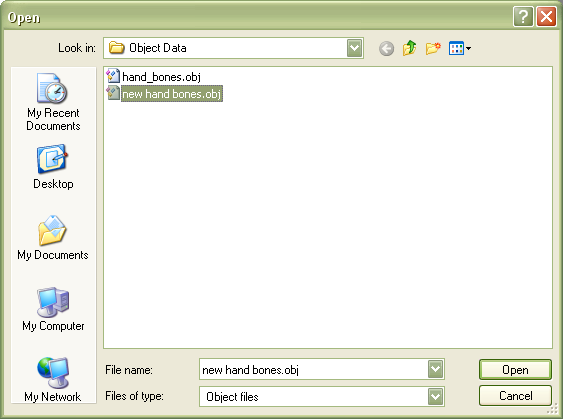
You can navigate to other folders but this is the default folder that is opened. You select and open the OBJ file you want to break up. That leaves you with something that looks like this...

...with the point cloud descriptor in List 1 and the triangle descriptors in List 2. When you've done that you then punch the Separate Parts button and wait for it to finish. It's pretty fast on my machine, but it can take a while depending on the complexity of what you are trying to separate.
Once it's done you can go find the Output folder which you can see here...
.
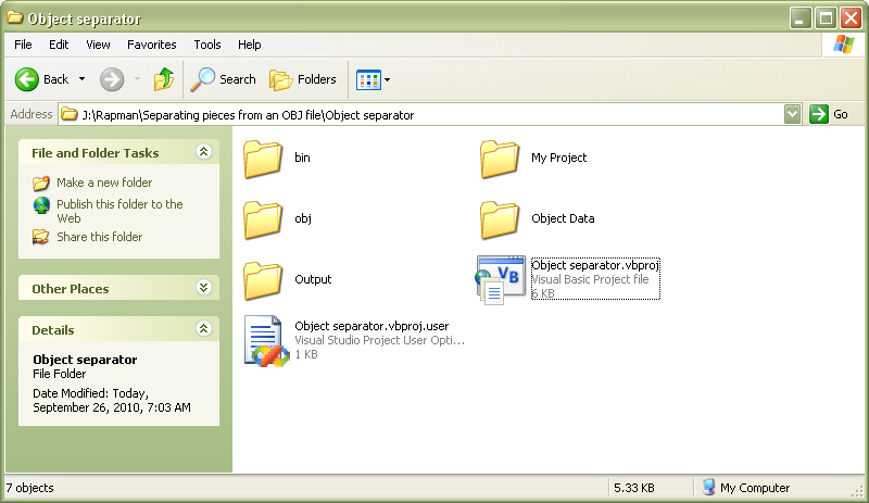
You can also see the Object Data folder in this pic.
Looking inside the Output folder, you will see that your original OBJ file has been broken into as many numbered files as there parts in your original OBJ file.

You can then take those into AoI and convert them to STL files for use with either my own Slice and Dice app, Skeinforge, Netfabb or any of the other apps that prepare print files from STL files.
You can see how this separation process works by looking at the #12 file of the hand assembly.

Like most of my work, I'm more interested in demonstrating methods and approaches than in creating out-of-the-box apps. I know most of you are much more interested in Java, the good Lord save you, and Python than the Wintel-only Visual Studio and Visual Basic development environment.
Have fun! :-D


