Thursday, July 29, 2010
Flexure achieved with the telepresence robot finger
Initially, I'd planned to use a Meka Robotics trick of using latex rubber as half of the system to control flexure. As it turned out, however, the quarter inch rubber bands that I had planned on using proved too weak in tension to do the job properly. Instead, I rigged the finger with nylon cord.
As you can see here, it works rather well.
Stiffness in the joints of the finger creates a requirement for a bit more axial force in the control lines that I'd like, so I will be slightly redesigning the joints for a somewhat looser fit.

Tuesday, July 27, 2010
A first finger
I began the telepresence hand design exercise using Andreas Maryanto's design as a starting point.

Andreas was kind enough to scan his design sketches for me which let me puzzle out the intricacies of his design.

Thanks to Google Translate my technical Bahasa Indonesia has improved dramatically. :-)
I took inspiration from several other places as well. Most notable was the Meka Robotics hand.

Their notion of using an elastic strip across the top of the fingers to return the hand to a rest state was very clever. As well, their notion of making the hand a modular unit was also very interesting. From these initial concepts I began to develop my own design.
To begin with, I own a personal Reprap-derived 3D printer. A Reprap printer is the functional equivalent of quite an expensive machine shop. It allows for a much freer design than either Andreas, cutting perspex or Meka, milling aluminum and plastic could hope for. After several false starts, I developed a joining approach which was rather easy to work with and print. Here you can see half of a distal phalange.

The middle phalange...

The proximal phalange...
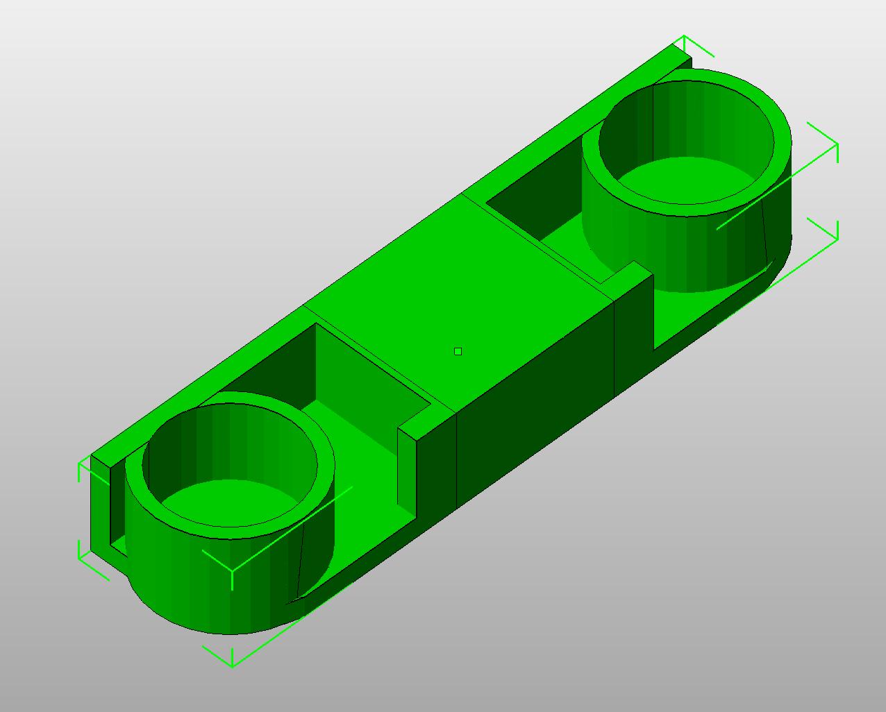
And the base knuckle and hand attachment of the finger...

I printed these parts without infill, as you can see in this printed and assembled distal phalange...

Here are a few pics of an assembled finger at various levels of flexure.


I use the Meka idea of a latex strip to return the finger to rest state except that I decided, for now at least, that rest state is going to be curled rather than extended. The design I've evolved lets the latex strips mostly reside inside the phalanges. The tendon in my design runs across the top of the finger and the servo driving the tendon pulls the finger into a fully extended state.
This approach allows for the latex strips to determine the maximum degree of grip that the hand can deliver. This should let me avoid having to use fingertip pressure sensors to determine the degree of pressure exerted by the hand. That is the theory, anyway.
My next step will be to install the latex strips and tendon. After than I will be designing the hand/servo assembly.
Wednesday, July 21, 2010
Refining and tuning
After refining the finger tip design a bit and tuning the print characteristics I got a much nicer product.

Now to redesign the next phalange.
Thursday, July 8, 2010
Tiny little steps
I finally got the Slice and Dice software for my Rapman 3D printer upgraded so that I can print parts for the telepresence hand project. That done, I ordered a fairly standard servo to play with so that I have something to develop my control firmware with and get used to the little ways of servo/microcontroller interfaces. I chose the Hitech HS-322HD, a coreless servo.

I already have a test board mounting a Microchip 18F4550 which I can hack to run the servo. It uses 5v DC current, which will be handy. I'm going to do a single finger for starts and use a melange of ideas from both Andreas' hand and the Meka robotic hand he showed me a few days ago.
The Meka hand uses a strip of latex rubber, a wide rubber band if you will, secured to the topside of the fingers to return the finger to extended position. That appears to be both simpler and less expensive than the spring system that Andreas used.
Friday, June 18, 2010
Telepresence hand
I ran across this project undertaken by an Indonesian engineering student, Andreas Maryanto, a few years back.
He uses servo driven wires in plastic tubing sheaths to drive the hand's movements.

He made the thing out of perspex (lucite), which could be easily laser cut. He built both sides of the rig.

His system is simple, cheap and, while not all that elegant in appearance, it appears to work quite well.
He uses servo driven wires in plastic tubing sheaths to drive the hand's movements.

He made the thing out of perspex (lucite), which could be easily laser cut. He built both sides of the rig.

His system is simple, cheap and, while not all that elegant in appearance, it appears to work quite well.
Sunday, June 13, 2010
Cheap and dirty laser range finding
One of the things that I want a telepresence 'bot to do is to be able to build up a 3D map of its environment pretty much autonomously. From previous experience, ultrasonic rangefinders are just too unreliable. That basically leaves me with either using a laser for direct measurement or offset trigonometric measurement. Until very recently direct measurement was simply too expensive. Recently, however, Stanly tools has put an inexpensive direct measurement unit on the market for a touch over US$80.

At that price, I'm a little hesitant about buying one of these and trying to hack it mostly because I'd hate breaking it. I've looked and looked and have yet to find a DIY schematic for this sort of thing. That leaves me wondering whether this unit uses very short pulses which would be eye-friendly or measures distance by overlaying the output pulse over the return and measuring the resultant offset. If it uses the second method, it could take too long to settle on a distance for eye safety.
I'm suspecting, however, that I can pulse a laser pointer fast enough to keep it well within eye safety limits. The design I slapped together places a web cam and a laser pointer pointed parallel to each other at a measured distance, in this case 29.4 cm.

As you can see, I placed a target 100 cm away from the camera lens.

The webcam that I am using grabs a 640x480 pixel RGB colour frame. That means that I have 320 pixels of resolution to play with.

Having chosen 39.4 cm put the laser dot right at the edge of the frame when I calibrated it at 100 cm. That left me with...
634 - 320 = 314
pixels of displacement for a distance of 1 meter.

I then did another frame grab of the kitchen cabinets. There I had
389 - 320 = 69 pixels of displacement
The distance to the center of the picture there is calculated...
314/69 = 4.55 meters
Physical measurement of the distance got me within about 2 cm of that. The difference is likely noise in my measurement and/or misalignment of my laser pointer.
I used a green laser pointer largely because for interior measurements green is easier to spot than red.
Subscribe to:
Posts (Atom)